Product Development Journey - TiledFlexi Keys: Part 2
Diving into Electronic Schematic of product development journey to build an end to end product
TL;DR
Continuation of Part 1 of the series to design and build an end to end product. This week I’ll be diving into designing the schematic for the system. This will include part selection, various microcontrollers families, Kicad process and few tricks learnt along the way. The schematic can be found below.
Tiledflexikeys Draft 12.76MB ∙ PDF fileDownloadDownload
Defining the system
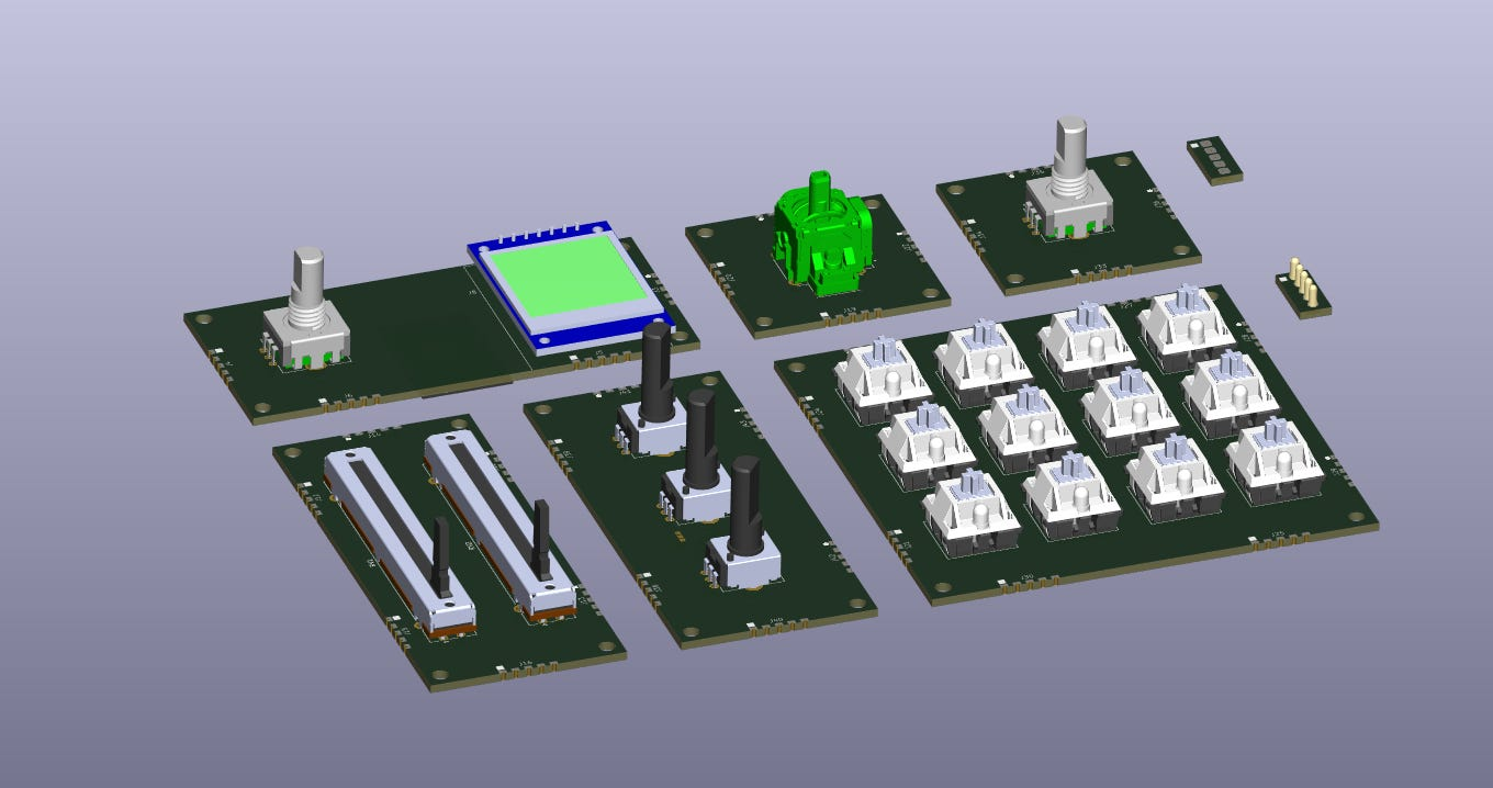
To begin with, I decided to break down the system into six modules. Each module with it’s own set of control and user can decide which modules does he need in his workflow. Further, we can add more modules as the project progresses.
Thanks for reading Rishabh’s Substack! Subscribe for free to receive new posts and support my work.
There modules would be
- Base Module
- Rotor x1 Module
- Slider x2 Module
- Knobs x3 Module
- Keys x12 Module
- Joystick x1 Module
The modules would look something like this but in an enclosure.

Base Module
The primary responsibility of base module would be PC communication, power, profile selection and communication with child unit. Based on these requirement, the design could further be broken down into blocks, major ones being USB, Power and Battery, Screen, Rotary Switch, Child Communication Interface. Alongside this, debug and programming interface for the microcontroller, block isolation and test points for debug and expandability were also considered in design process.
Microcontroller
Choosing the microcontroller was the first part of the project. As one of the aspect of this project was to familiarize myself with different development environments and processes, I chose different MCU for each module. For this module though, I decided to choose something I’m more familiar with and which is powerful enough for future expansion.
I decided to go with ESP32-S3 Wroom module. This module along with having enough processing power to run micropython also has WiFi and BLE for wireless communication. Plus it has enough memory to have different user profiles loaded into the same along side firmware. Another handy feature is support for USB and other peripherals like GPIO, ADC, I2C, UART, SPI, QSPI plus tons of resources online to get started with.
For minimal schematic, it’s best to look at the schematic of dev kit along with datasheet to understand the logic behind the design. References to design and schematic can be found here. One major change I made though was add USB C instead of microusb.
USB C
USB C, the boon and curse of electronic connectors. The boon part is the connector and protocols have tons of consideration put into them to support high data rates, power negotiations which also being backward compatible with older or slower and less power consuming applications. The curse rises out of exactly the same consideration, being so feature rich, the connector cost, cable cost become high and manufacturers came up with 10 different variations of connectors with different capabilities not to mention 10 different cable types not everything supports every feature. And there is less uniformity on these connectors to make them replaceable if they go out of stick since footprint are not one to one compatible before analysing them in detail.
For my application, I didn’t need high bandwidth or power delivery. 5-10W of default power would be more than enough for the application and since the need for USB is only USB 2.0, I can get rid of most of the differential pins for USB 3.0 and above.
I decided to select the connector GSB1C411111DS1HR. This had just enough pins to support my application further reducing soldering complexity as well. Another consideration would be to have footprint compatible part from lcsc which would give a good cost advantage. The problem though was scrubbing through datasheet written in language I don’t understand. I was able to select something though.
Connections to USB C includes,
- 5.1K pull down resistor on CC1 and CC2 pin which instructs the power network that it needs to drain 5V power. VBUS
- ESD protection diode of communication and power pins
- Reverse Power protection diode on VBUS.
Power and Battery Management
Power design for the system includes taking power from USB when available, scaling it down 4.2V to charge the Li Ion battery. Then either taking power from USB or Li Ion and converting it to 3.3V using buck convertor to supply to microcontrollers also scaling it up to 5V using boost converter for some peripherals like addressable RGB Led.
The major IC’s selected were
- MCP73831-2-OT for battery charging
- MIC2288YD5-TR for boost converter
- TLV62568DBV for buck converter
The power design calculations are not completed yet but I found a awesome video by Phil’s lab explaining the sizing of components.
Rotary Switch
I wanted an interface which could act as continuous scrolling through profiles and also click to select a particular profile. Rotary encoder fits the application. I seldcted PEC12R-4125F-S0012 for the application. One thing to consider when using these is the shaft size does need to fit your mechanical design constraints as well to come out of enclosure, so you might have to come back to this part after the mechanical design is under way.
Screen
Finding a colored screen for the application around 1 inch was a challenge. Although there are multiple options available, most of them are either costly or had constraints on features I wanted like color and size. Finally, I decided to choose this screen from aliexpress. Although risky, one reason for the same was to explore aliexpress as sourcing channel for certain components. Also, since the interface is I2C, I could replace it with a known screen if I wanted at a later stage as it is not necessarily tied to PCB footprint.
Child Communication Interface
The module would communicate with child module using I2C along with a interrupt line. Each module would have a pogo interface on two sides and landing pads on other two sides. These modules would snap together using magnets and link to each other for communication. The interrupt would be issued by the child module on user action which would then result in base module polling the modules for event and transmitting it to PC.
Other Parts
One consideration in the design was to add 0 ohm resistor and test point between each major block for isolating them and testing them. USB to UART was also added using CP2102N-A02-GQFN28 for debugging if needed. Top touch down pads were added to the product to streamline programming and testing in production environment.
Rotor x1 Module
The next module and the simplest one is Rotor x1 Module which as the name suggest contains one rotary switch. This module can be linked to any application where continuous scrolling is needed. e.g. of such would be continuous zoom in/out, scroll etc.
For this module, the microcontroller chosen was PIC18LF4331-IML. Although the microcontroller is way more powerful and feature rich then it needs to be, it does have rotary encoder reader as peripheral which I wanted to look into. Also, this would give me option to look into PIC development environment.
Slider x2 Module
This module would contain 2x linear sliders. This could be linked to operations on PC which has upper and lower limit. Something like brightness, volume, transparency or MIDI controls etc.
As for the linear slider, I selected a linear potentiometer PTA4543-2015DPB103. Interfacing this with microcontroller would be a simple ADC reads.
For the microcontroller, I selected CH32V003JxMx controller. Although completely new for me, the controller is the most cost effective solution available in market costing just 20 cents while being programmable and based on RISC V plus having most necessary peripherals.
Knobs x3 Module
Knobs module is similar to linear slider in application but provides rotational interface instead of sliding it. The application could be something like setting RGB in photoshop using physical knobs.
For this module, I chose STM32F103C8T6 MCU. Again, the controller itself is overkill for application but would give me more exposure into STM32 controllers. Another reason for the same is it has a bluepill development board readily available to test firmware even before receiving boards.
Keys x12 Module
This module would have 12 mechanical keys which could be mapped to any keyboard shortcut based on the workflow, something as simple as copy using single key or tool change while using CAD or compile and deploy code with single button.
For this, I chose RP2040 microcontroller just for exploration and since the microcontroller has a package which is not all that simple to solder plus the mcu needs few external components more than other counterparts.
Joystick x1 Module
Joystick or Thumbstick module could be used where we need more degree of freedom like spacemouse for rotating 3D models or scrolling 2 directions at once.
The joystick selected was THB001P. Similar to other modules, one thing to consider would be mechanical constraints to expose out of enclosure.
The microcontroller selected for this is ATtiny841-SS. Having just enough pins and features while being cost controlled.
Schematics Tips
For designing schematic, here are some tips and good practices learnt along the way.
- Use Hierarchical sheets, start with defining blocks, with systematic purpose and I/O for each module. This doesn’t just makes schematic easy to read but also gives a top level view into planning tests, isolations, mapping for signals.
- Use SnapEDA or online libraries for symbol, footprint and 3D model. These modules would need cleaning up for part numbers and BoM generation. Also, you might want to edit local symbol for easier flow of signals.
- Use version control using git. Store all needed resources like additional symbols, models in the same directory.
- Leave notes and design calculations in schematic. This makes schematic one source of truth for most needed items.
What’s Next?
Next week, I plan to dig into mechanical enclosure design aspect of the project. This would first explore the mechanical design in Fusion 360 and 3D printing it. Also, tips and tricks for parametric designs. And then also diving into automating design generation in Fusion 360 using Python which was super fun and exciting to play with to automate multiple of such enclosures.
Thanks for reading Rishabh’s Substack! Subscribe for free to receive new posts and support my work.