Product Development Journey: TiledFlexi Keys - Part 3
Into 3D modelling the enclosure

TL;DR
This article is continuation of the product development journey series. While Part 1 deals with the concept design and decisions, Part 2 dives into schematic design. This part will dive into 3D modelling of enclosure using Fusion 360. Along with design and some learnings along the way, one major learning was using Fusion API to dynamically create the model using programming. This can be used to repeatedly create similar structures or repeat a part of the process.
Tool
For CAD modelling, I used Fusion 360. While there are few too many tools out there from Solidworks, OnShape, Fusion 360 along with some open source tools like FreeCAD and OpenScad. I explored FreeCAD first and found it to be lacking in features and had a non intuitive UI. Onshape though had a good offering was lacking a private project trial feature. Finally, I found Fusion360 to be a viable option with good features, 10 private projects to try things out and intuitive UI.
Thanks for reading Rishabh’s Substack! Subscribe for free to receive new posts and support my work.
Trying things out and learnings early on
Trying 3D CAD for the first time, the journey had quite a lot to teach me. Like every skill, the journey started with couple of youtube videos and examples out. I was equally focused on processes and design for this project. After mockups and failures, the two most important lessons learnt were
- Make design parametric.
- Select constraints and dependent dimensions carefully
The biggest decision in your project is going to be the initial sketch, what might need to be changed in future and what dimension or constraint will depend what. After few rough concept designs and dirty mockups, we need to define the parameters. Parameters are variables that can change in future and the design updates automatically (only if constraints are well defined)

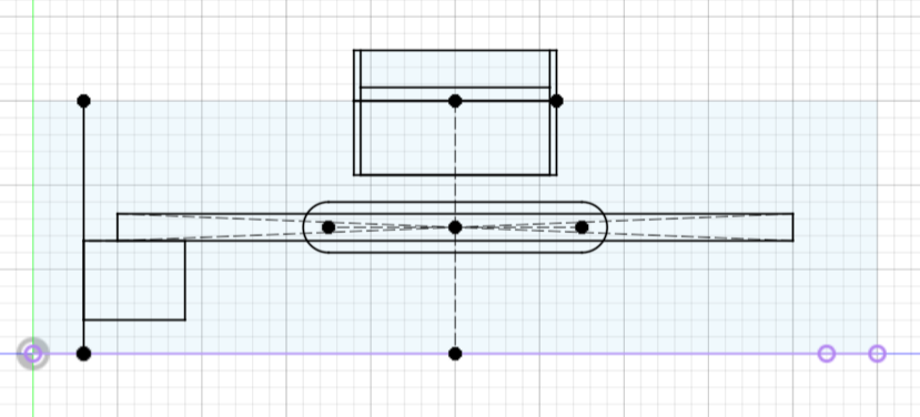
After defining the parameters, we start the sketch. But before that, we need to decide on reference planes. This depends a lot on the direction of features that you want. Generally your sketch would have multiple sketches on various faces. For e.g. my simple base sketch look like this.

And even though it seems like all dimensions are hard coded, they are variables coming from well calculated parameters.

The outer border over here (3mm) is the side wall projection.
After the sketch, we extrude various features to create base and walls.
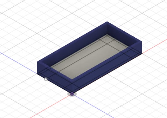
Then taking left wall as reference, create and extrude slots and snap.


And then similarly comes top plate, snaps, magnet insertions, PCB base, threads, USB C. Also, pattern repeat parametrically.
Finally, we get something like …….
First Prototype printing
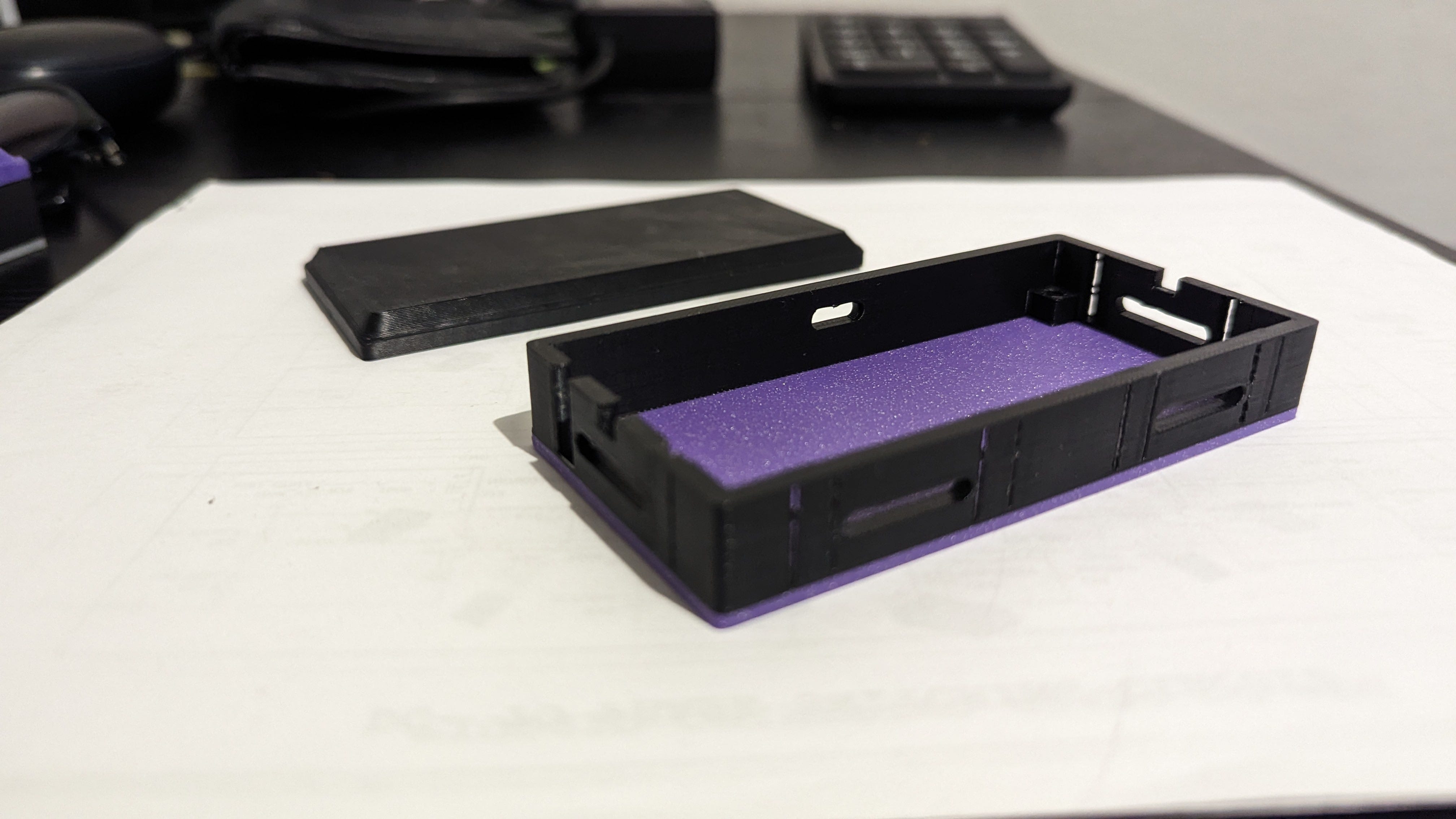
Here comes most interesting part for an engineer in any project “Does it work?”. With a friend’s Bamboo X1 Carbon, I went for my first 3D print. Using Bamboo Slicer, I played around with various support structures and parameters to fine tune how I want the 3D print to come out. The model being multifilament, gave me freedom to actually print the item in multicolor.
Lessons from first print
Well, that turned out slightly worse than fine. There were few mistakes clearly visible, like warping around the magnet cut, snap being too small and thin and magnet not fitting the slots.
Major lessons learnt from the first print
- Remember to consider nozzle diameter while designing, any feature less than twice the nozzle width in horizontal direction is going to be omitted. Better, make this as parameter and use it in design because your 3D printer might change and during design you might not be aware of the printer you’ll get to manufacture this on.
- CAD is infinitely zoomable but real world is not. Things seems big or small based on zoom level in CAD. Though the snap and details looked fine in CAD, they were too small to be printed.
- Remember and account for tolerances. Specially if you’re designing for snap fits which is super neat but needs experimentation.
- Warpage and overhangs do affect the quality
- Some post processing might be needed before using this as final enclosure for surface finish
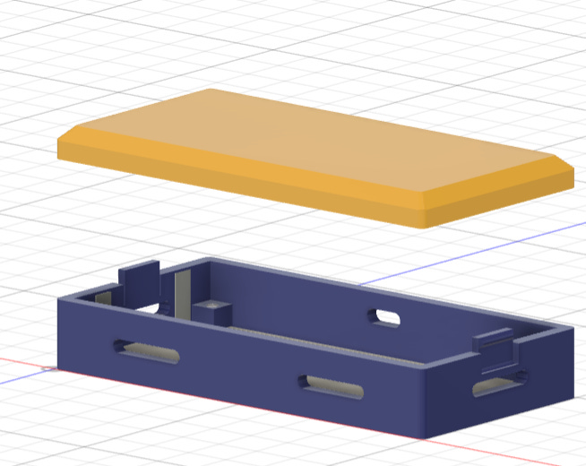
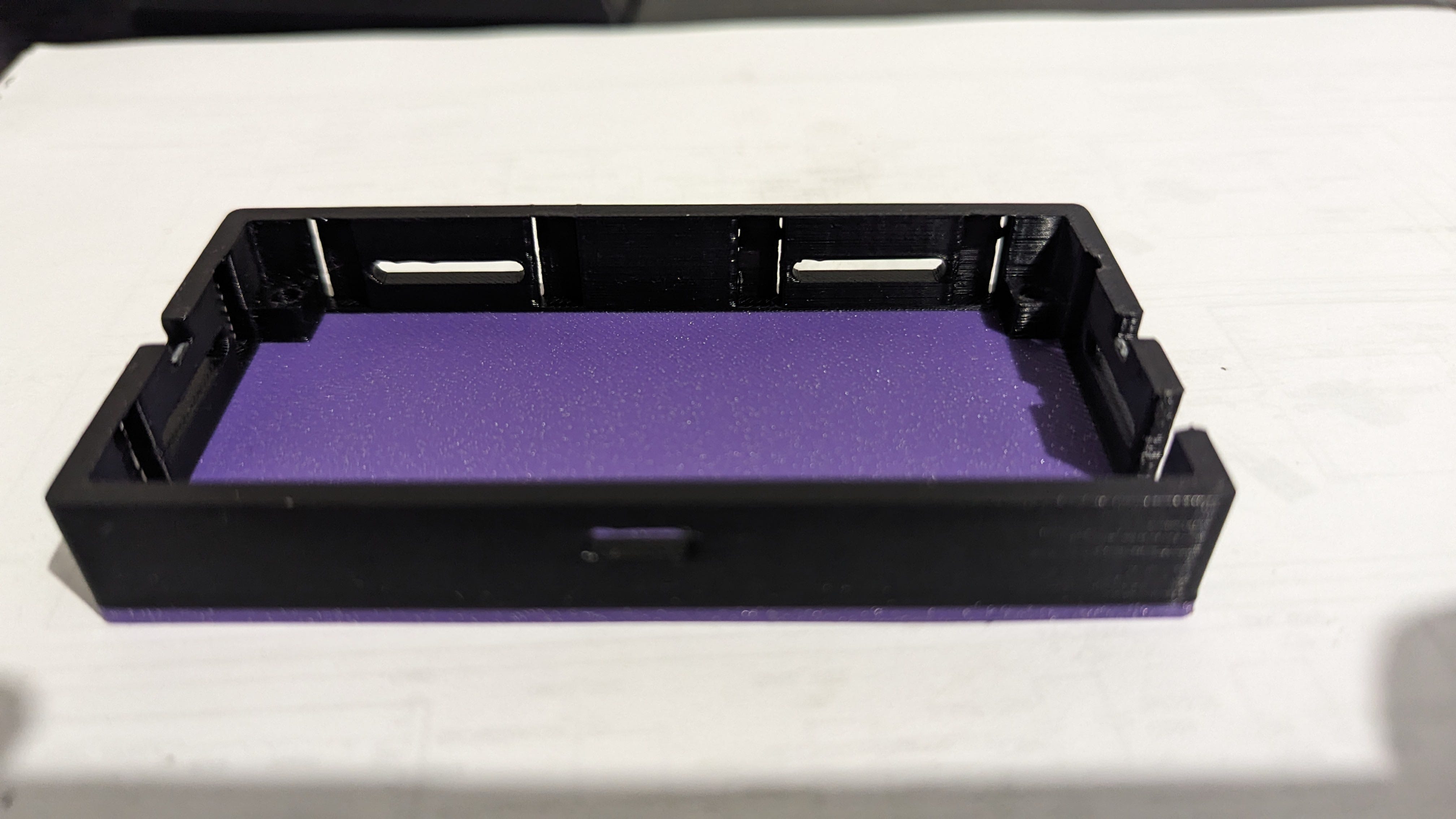
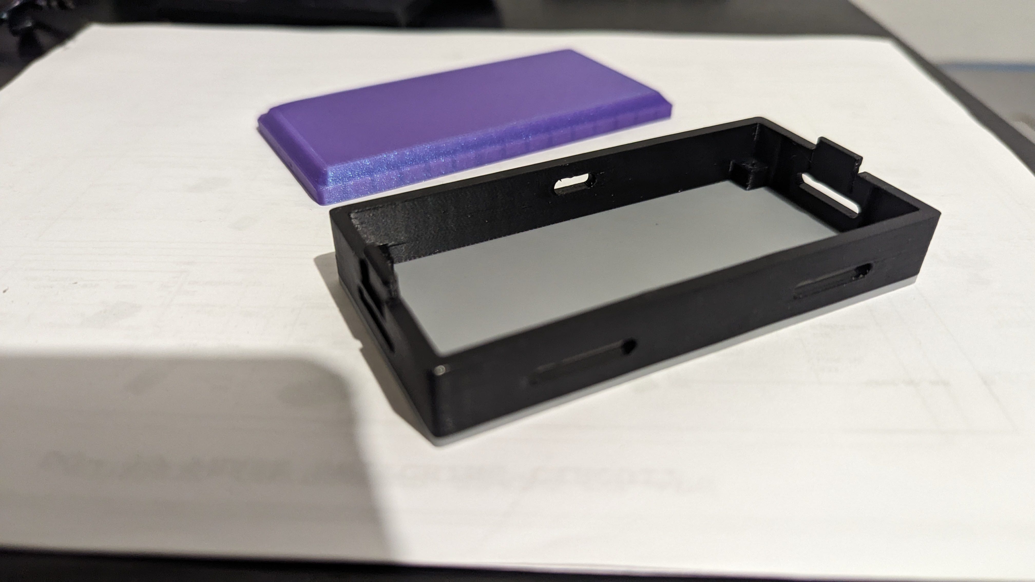
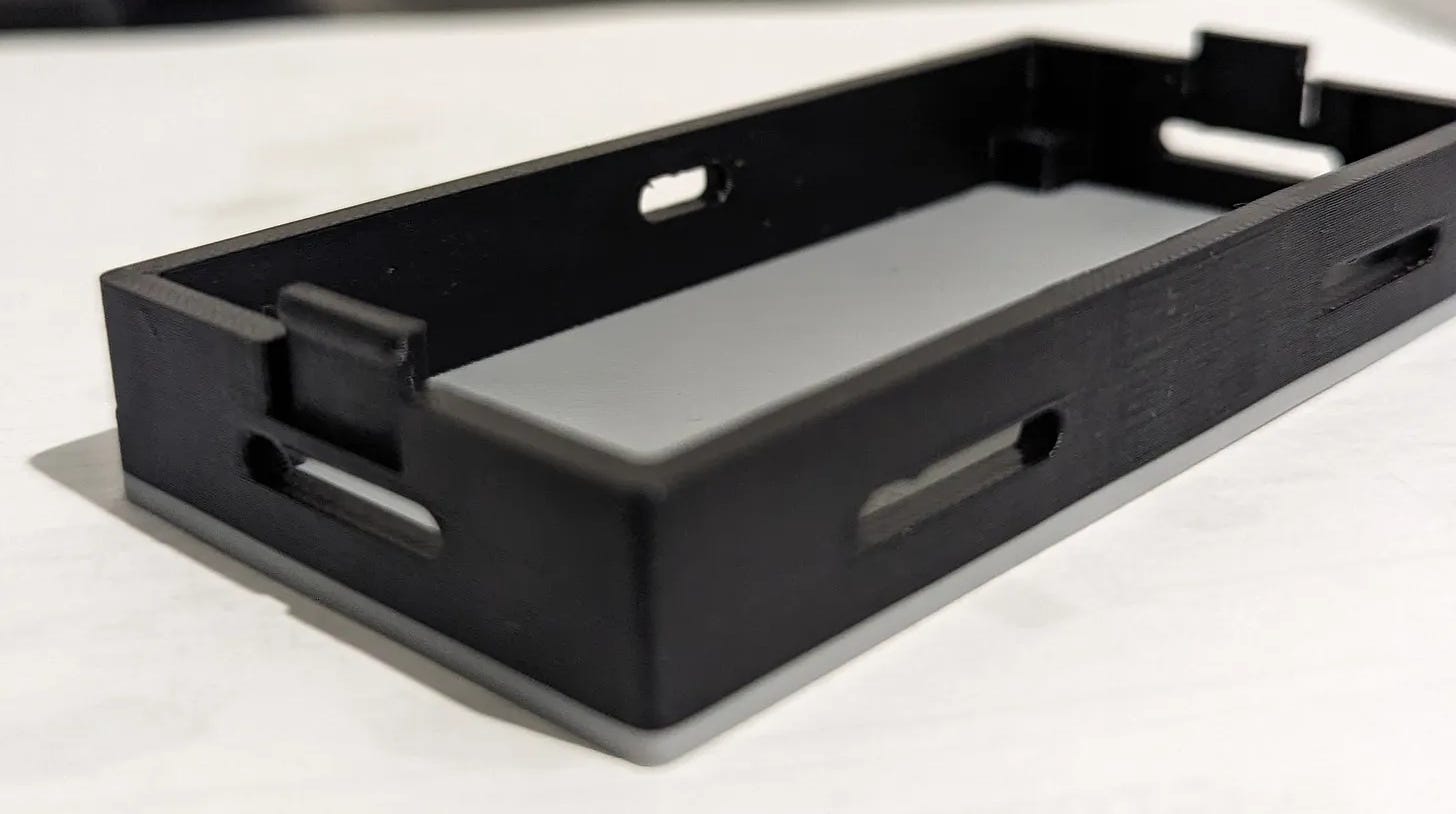
After going back to design board and fixing these, comes the next version which turned out a LOT better than first being very close to how I want my final box to look and feel. I also included chamfers, round cuts in the design for it to feel much better.


And Repeat (Thanks API)
Now that I have the base ready, I had three conundrums.
- I need to repeat this base for every module which I make which is boring and repetitive
- The design is not finalized, so anything even if it’s small, if it changes in early sketches will affect the complete design and might break stuff
- Any change which I make to one model will have to be repeated for all modules consistently
And the solution? Fusion 360 API to create the design programmatically.
Now, even though the API is well documented, it’s a bit counter intuitive to get used to. Also, it’s penetration is not too high in community since the mechanical engineer or CAD engineer primary using the tool are not very active programmers and CAD design is a very visual process. Because of less penetration, the number of tutorials or user developed material on the topic is a bit less. Luckily, I’m decently good at Python and programming and thankfully, it’s 2024 so we have ChatGPT for help.
I broke down the model into steps
- Create user parameters
- Create Base sketch
- Extrude base and walls, PCB holder
- Create left wall sketch (with slots, snaps and magnet cuts)
- Create front wall sketch (with slots and magnet cuts)
- Cut necessary sections from sketch to create openings and slots
- Create PCB holder sketch
- Create chamfers and round cuts
- Create patterns for repeating the cuts multiple times
- Create reference planes and mirror the sections
- Create top plate
- Create snap cuts on top plate
All of these could be done programmatically, although slow, this makes the process much more systematic. The few benefits this offers are
- Any change you want to make in the design, using programming can be used to generate all models within minutes rather than repeating the complete process from start
- The code can be version controlled making debugging considerably simpler and easy to fix
Downsides of API Approach
Yes, I found API approach a lot interesting but there are couples of downsides to the approach.
First, the approach is not suitable for all processes, in fact this is only useful if you want designs to be repeatable. Some examples could be PCB enclosures, motor cores etc. Having said that, this the approach is also useful if you want to automate partial processes which are repeated in a single design. Something like adding holes of particular dimension at various places or clubbing couple of processes which always follow one another in single click.
Second, it’s difficult to select an object or see selections since rarely are those named and it’s difficult to see visually what is getting selected. Generally selections like faces, profiles, planes, extrudes are indexed i.e. they have a number in the array instead of named i.e. having unique name. This makes the selection a little tricky and finding the index is a bit troublesome. Some features can be named and selections can be made using name but others, you have to try indexes till one fit. Thankfully this is generally repeatable and just depends of sequence of operation. The easiest solution is to have some of the selections manual i.e. prompt user to select the profile which they want to cut or face where they want sketch to be made.
Using hybrid approach works best for the design where you automate only repetitive processes but keep selections and unique designs still manual.
Getting started with the approach
Where do we even find the option?
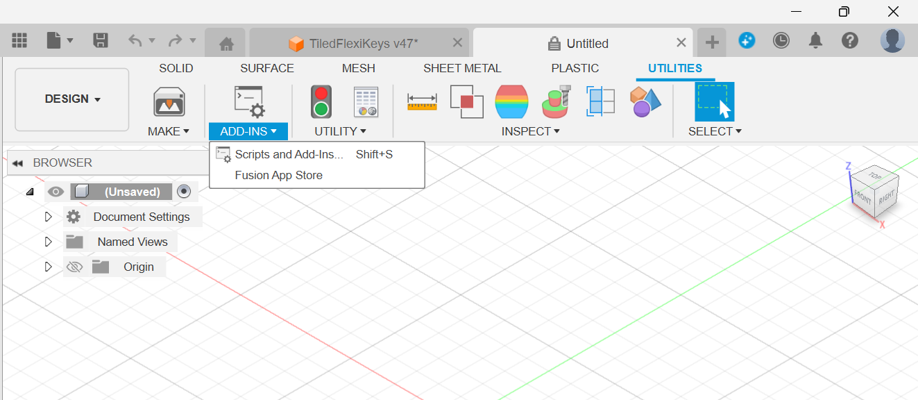
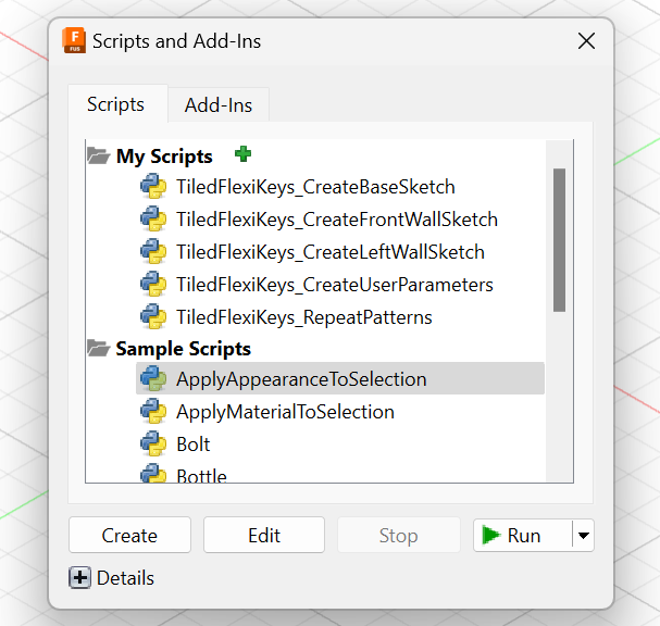
Next, how do I get started.
I referred the following resources
- Youtube playlist by Learn Everything About Design
- Documentation by Autodesk
- ChatGPT (GPT4 over 3.5 is HIGHLY preferred)
Using it in my design
Since for me the steps were very clear. I started writing, playing around with the scripts. Though the design is still only 30% done, the approach is quite clear.
There is individual script for each of the step listed above and you approach them one after other. First create the user parameters, then base sketch, walls, left wall sketch, front wall sketch, patterns and so on.
What’s next
Till now, we have explored parts of the concept, system design, schematic design and 3D modelling. The untouched topics till now are PCB design, firmware design, manufacturing parts of which I plan on getting to next. Then I’ll reiterate few of the already covered topics for revisions and modifications made.
In next article, I’ll probably be covering my journey of PCB designing for this project.
Thanks for reading Rishabh’s Substack! Subscribe for free to receive new posts and support my work.